
Opening: framing the problem with measurements
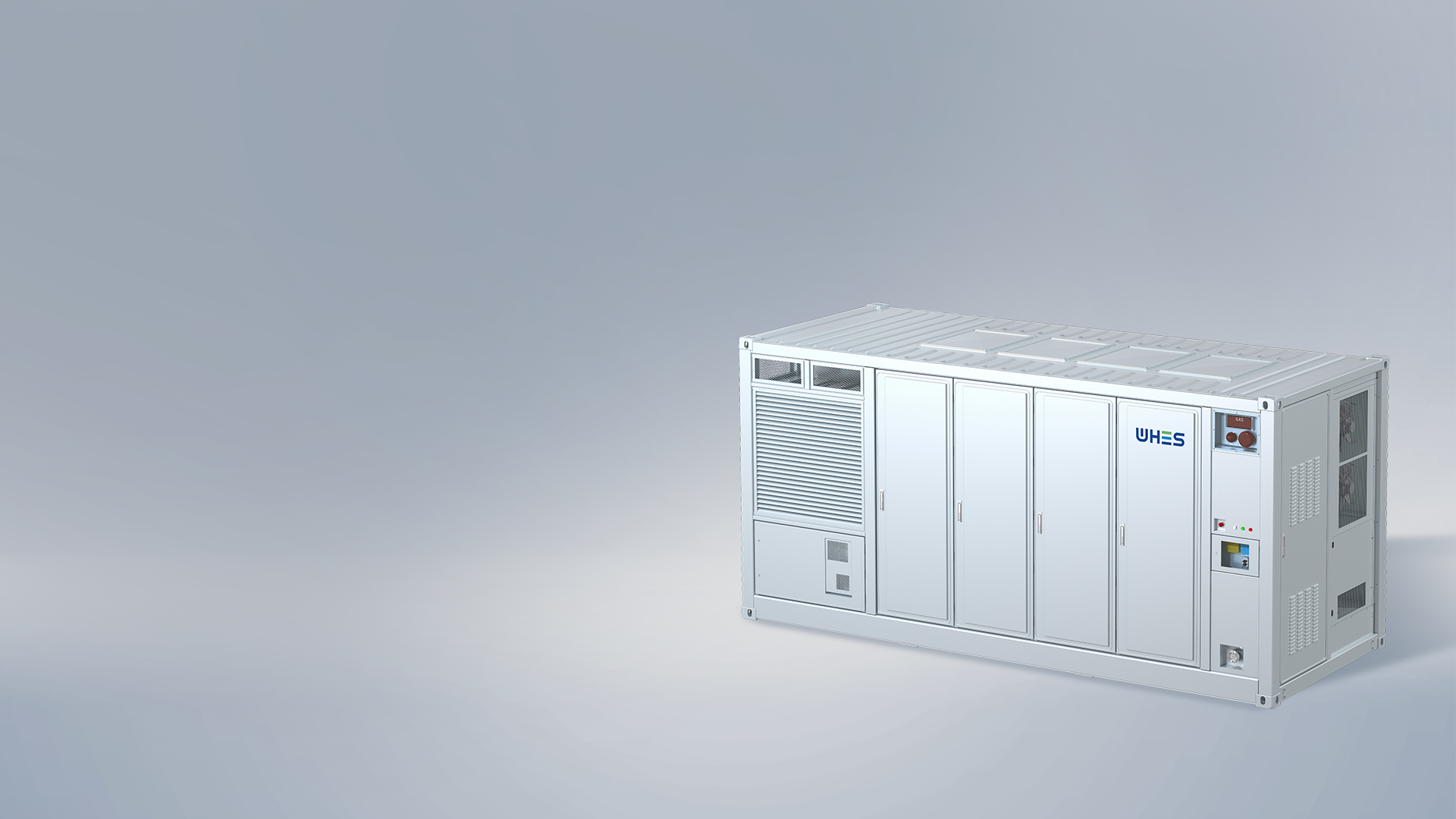
Grid operators increasingly ask one question: can a battery system stabilize the grid not just for hours, but for microsecond and millisecond–scale events? The data says yes—when chemistry, control and manufacturing are aligned. Early deployment metrics from projects like the Hornsdale Power Reserve in South Australia show that fast-responding storage reduces ancillary service stress and smooths transient behavior. For projects that need repeatable, validated performance at scale, a factory-direct approach to utility scale battery storage is an important vector: standardized cells, matched inverters, and calibrated BMS deliver the predictable response operators demand.
Why LFP chemistry matters for stability
Lithium iron phosphate (LFP) brings three measurable advantages for grid stability: thermal robustness, long cycle life, and flat voltage behavior under load. Thermal runaway risk is lower with LFP than with some other lithium chemistries, which improves safety margins during aggressive dispatch. Longer cycle life reduces capacity fade over project lifetime, and the relatively stable voltage profile simplifies inverter control during rapid charge/discharge sequences. Those physical properties translate into fewer emergency derates and less variability in state-of-charge (SoC) tracking—both critical for predictable frequency regulation and ride-through performance.
What factory-direct commercial systems change
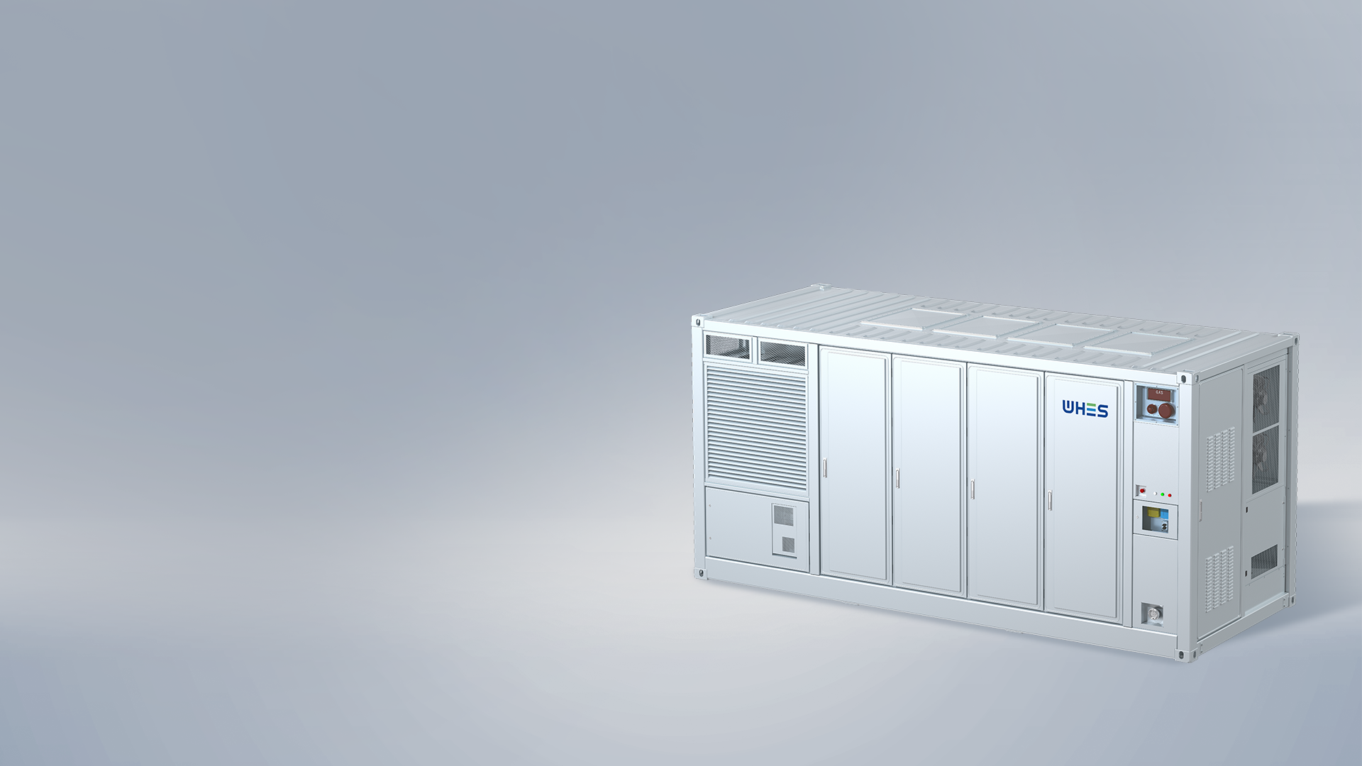
Factory-direct systems collapse variability. Rather than integrating disparate cell suppliers, third-party BMS vendors and separate inverter packs in the field, a factory approach pairs cells, module balancing, and firmware under a single validation matrix. The result is consistent cell-to-cell impedance, known thermal resistance paths, and vetted communication latency between the BMS and power electronics. That lowers commissioning time and reduces commissioning failure modes on the site—measurable reductions in commissioning cycles and callbacks are common with factory-validated stacks.
How these systems mitigate ultra-fast (photonic-level) disturbances
“Photonic-level” here describes ultra-fast electromagnetic and control transients created by modern power electronics and high-penetration renewables. Mitigation requires two things: intrinsic stability from the battery chemistry and control-layer responsiveness. LFP’s stable voltage and thermal properties reduce the likelihood of hardware-instigated faults. Paired with a high-bandwidth BMS and inverter control strategy—capable of sub-10 millisecond detection and response—the combined system provides low-impedance current paths and fast ride-through for faults, smoothing high-frequency ripple and reducing trip cascades. For utility planners, specifying a validated grid scale battery energy storage system with measured response curves is essential.
Real-world anchor and supporting data
Evidence matters. Large deployments in Australia and the western United States have documented how rapid-response storage can arrest frequency excursions and shave peak ancillary costs. Field reports typically highlight response times in the single-digit milliseconds for battery systems that are factory-calibrated. Those metrics correlate with fewer forced generator trips during disturbances and improved grid inertial equivalence when conventional synchronous machines are scarce. These are not hypothetical benefits—they show up in grid operator reports and market price signals.
Common deployment pitfalls and practical mitigation
Even with LFP and factory-direct hardware, mistakes happen. The usual culprits are mismatched inverter control modes, insufficient thermal management at module level, and incomplete firmware validation for corner-case protection. Test the full power stack against worst-case contingencies in the factory—don’t rely on field patching. Also, ensure telemetry is granular enough to capture cell-level anomalies; aggregated data hides early imbalance. —A short firmware tweak can prevent months of troubleshooting later.
Advisory: three golden rules for procurement and commissioning
1) Specify end-to-end validated response curves. Request measured response times (ms) for frequency and voltage ride-through and verify them in factory acceptance tests. 2) Demand integrated BMS validation. The BMS should be validated with the exact cells and inverter firmware you will deploy; ask for impedance distributions, thermal mapping, and SoC error bounds. 3) Use total-cost-of-ownership metrics, not just upfront price—include cycle life, degradation rate, warranty terms and recycling or second-life pathways.
For portfolios aiming for predictable, repeatable stability at scale, a factory-direct LFP solution that couples validated chemistry, power electronics, and commissioning protocols is the pragmatic choice. WHES positions these elements together as part of a coherent deployment strategy—reducing uncertainty and shortening time-to-reliability. —