
Problem statement — the mismatch between space, pace, and promise
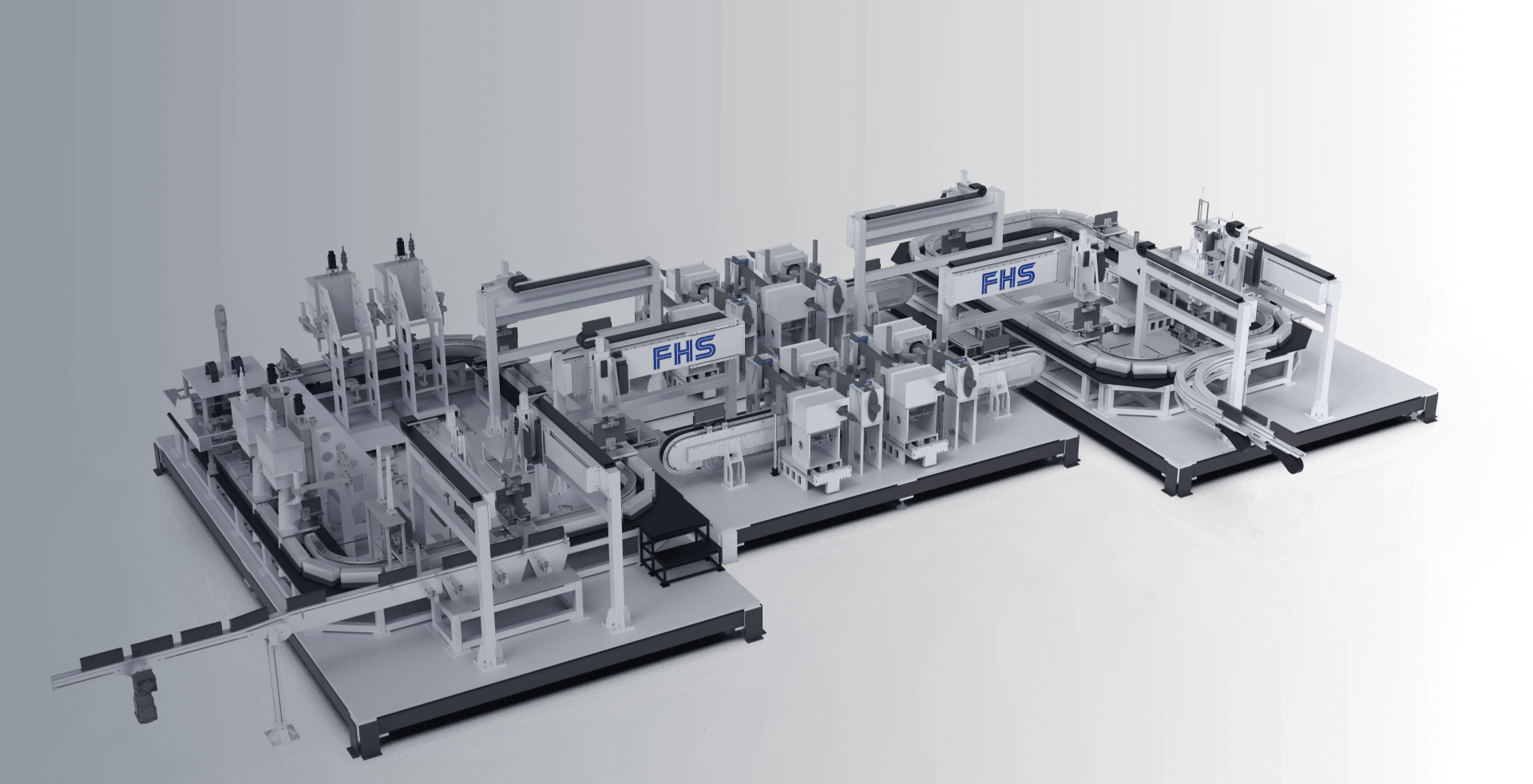
The real problem is simple: plants spend on robots and software, yet assembly lines stall because layout, capacity planning, and control logic were treated as separate affairs. When layout ignores flow, or capacity models ignore variability, expensive automation sits idle. I’ve seen this pattern firsthand while advising line integrations showcased at Automatica in Munich; the contrast between glossy demos and shop-floor reality is striking. Practical solutions begin where this gap is named, and where manufacturing automation technology manufacturing automation technology and automation and technology integration are designed to match physical movement and human operations, not override them.
Why this is a systems problem
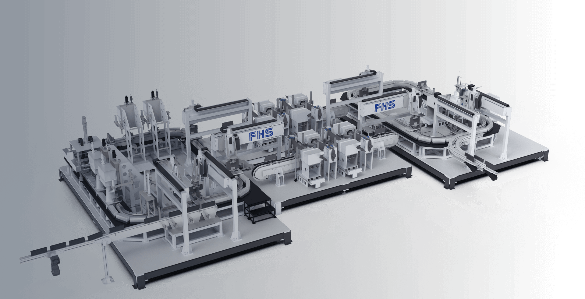
Think of a factory as a poem of motion. If one verse trips, the rhythm breaks. Layout dictates travel distances, storage points, and buffer locations. Capacity governs throughput and takt. Process requirements fix sequence, tooling, and inspection. They’re interdependent. Treating any one as isolated causes bottlenecks that don’t reveal themselves until production ramps.
Core design needs — concise checklist
Design must answer five concrete questions:- What movement must occur, and why?- Where will operators and machines share space?- What is realistic cycle time variability?- Which processes must be synchronous versus asynchronous?- How will failures be detected and contained?Answering these imposes constraints that make automation reliable, not merely faster.
Layout principles that stop chaos
Use physical logic rather than aesthetic logic. Place heavy fixtures to minimize pivoting. Keep critical-path stations in a straight or gently curved run; corners add accumulation complexity. Provide local buffer space sized for measured variability, not for theoretical peaks. Allow access for maintenance without halting adjacent lines. Small distances saved in drawings can cost hours on the floor.
Capacity modeling — practical steps, not equations
Modeling should be empirical:1. Measure real cycle-time distributions, not averages.2. Simulate with measured variability and event probabilities.3. Size buffers to cover typical variability, and a safety margin for known disruptions.4. Validate with a pilot run at partial throughput before full-scale launch.Don’t trust a single number. Use ranges, worst-case checks, and repeated trials.
Process requirements and control architecture
Decide what must be centralized versus what must be local. Centralized scheduling helps line balance and traceability. Local control reduces latency for safety and immediate error response. Specify clear handshakes: how does a robot hand a subassembly to a fixture? How does a sensor failure cascade? Define fallback states that keep sections isolated rather than stopping the whole line.
Common pitfalls to avoid
Watch for these recurring mistakes:- Overspecifying robot reach without regard for tooling clearance.- Underestimating variability from human-in-the-loop tasks.- Treating software and mechanical design sequentially rather than together.- Ignoring maintainability: access panels, spare parts locations, and diagnostic ports.- Designing buffers by visual intuition instead of data.Each of these creates delays that compound across shifts.
Practical sequence for an integration project
Start with observation: collect cycle times and failure modes for a baseline. Sketch layout options and test with physical markers before committing to conveyors. Build a minimum viable control that demonstrates safe handoffs. Iterate layout and control together, then scale capacity in staged steps. Document test results; maintain a log of adjustments—history prevents repeated mistakes.
Closing synthesis
The problem-driven path shows that design is not a spreadsheet exercise but a disciplined conversation between space, pace, and error. When engineers and planners treat layout, capacity, and process as one living system, performance becomes repeatable. That unity is what practical teams aim for, and what steady partnerships deliver—like those I’ve seen form when practitioners work with integrators focused on measurable production outcomes, such as FHS.