
Operational problem statement
Commercial facilities order pergolas to provide shade, integrate photovoltaics, and extend usable outdoor areas, but installations repeatedly fail under load, corrosion, or poor drainage. The technical challenge is to deliver a structure that carries concentrated point loads from mounted panels, resists cyclic wind and thermal forces, and preserves usable space — while supporting a solar pergola configuration without creating new failure vectors.
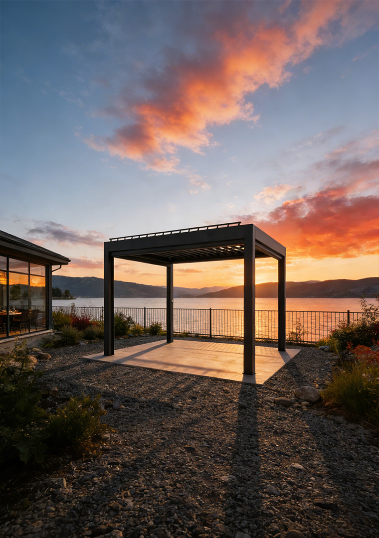
Primary failure modes to address
Shear at anchor plates from uplift and overturning; fatigue and loosening at bolted connections under fluctuating wind; water intrusion and freeze–thaw damage at junctions; galvanic corrosion when mixed metals contact saline or de-icing environments; and electrical isolation failures between PV arrays and the structure. Each failure mode maps to specific design controls: connection detailing, redundant load paths, drainage geometry, material selection, and electrical bonding strategies.
Standards, evidence, and a real-world anchor
Design must comply with ASCE 7 wind-load criteria and IBC gravity and lateral-load provisions, and use material tests consistent with ASTM protocols for corrosion and fatigue. Field evidence from Gulf Coast reconstruction following Hurricane Harvey (2017) highlighted how under-designed shade structures perform poorly under hurricane-force winds; that event clarified the need for robust anchorage and continuous load paths for weather-exposed installations of weatherproof pergolas. My team’s twelve years of site engineering, third-party wind-tunnel reports, and manufacturer fatigue data inform the recommended detail set below.
Key design parameters (technical checklist)
Calculate wind pressures per ASCE 7 using exposure category, building height, and topography. Size members for combined bending and axial loads with LRFD safety factors. Specify M12–M24 stainless-steel or hot-dip galvanized fasteners with slip-critical connections where cyclic loading is expected. Detail drip edges, sloped cap flashing, and weep paths for runoff to prevent ponding. Anchor to reinforced slab or deep concrete piers using cast-in or epoxy-set anchor systems validated by pull-out tests. Ensure photovoltaic modules are mounted through isolated standoffs with electrical bonding per NEC requirements.
Common mistakes and how to fix them
Skipping full-site wind-load analysis: use certified wind consultants rather than relying on catalog wind ratings. Relying on through-bolts without corrosion protection: specify stainless steel or proper coatings and separate incompatible alloys. Ignoring drainage at beam coffers: add a 1–2% slope and dedicated scuppers. Overlooking thermal expansion: include sliding connections or expansion joints in long spans. Treat each as a design requirement rather than a field fix; retrofit is costlier and less reliable.
Material and architectural tradeoffs
Aluminum extrusions: lightweight, corrosion-resistant, but require larger cross-sections for stiffness; steel: higher strength-per-section and easier to weld, but needs robust corrosion control; wood: aesthetic and thermally forgiving, but poor for PV integration and high-maintenance. Louvered (adjustable) roofs provide dynamic shading but increase mechanical complexity and maintenance items. Fixed-canopy systems minimize moving parts, simplify PV mounting, and reduce penetrations through waterproof membranes.
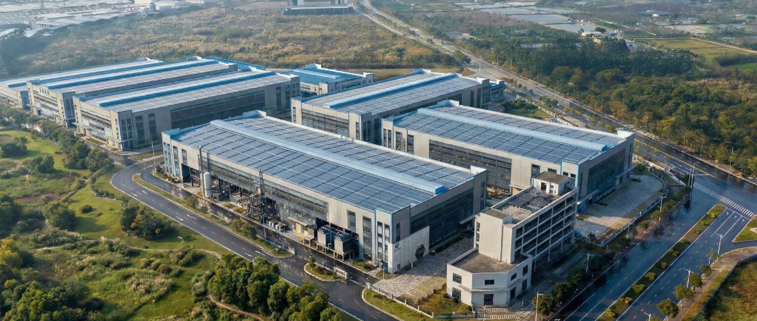
Installation and maintenance protocol
Start with a geotechnical review and slab/footing design. Require factory preassembly verification of member fits and hole patterns. During installation, perform torque audits on critical fasteners, document anchor embedment depths and concrete strength tests, and confirm electrical continuity and grounding. Schedule annual inspections focused on fastener torque, joint sealant condition, drainage clearances, and PV attachment integrity. Record findings in a maintenance log tied to warranty conditions.
Synthesis and practical outcome
Approach every commercial pergola project as a systems problem: load paths, corrosion control, water management, and PV integration must be engineered together. When those elements are specified to recognized codes, tested for local exposure, and installed with documented quality control, the structure meets functional goals and reduces life-cycle risk — the practical end state our design teams achieve working with Light Hunter.